How to build an AMD AM4 socket PC
In this guide, I will show you how to build a PC that uses the AMD AM4 motherboard socket and the ATX form-factor.
To keep this guide short, I will assume you have these components:
- A case which uses the ATX form-factor
- A non-modular power supply
- AM4 Motherboard that uses the ATX form-factor (in this guide I use an Asrock B450m-HDV r4.0 for examples)
- An AMD AM4 Ryzen CPU
- AM4 fan heatsink cooler for the CPU
- 2 sticks of DDR4 RAM (Random Access Memory) (Dual Channel)
- PCI-E x16 graphics card
- 2.5inch SATA SSD
I will also not attempt to explain everything, since there is videos which show how it can be done, this guide can be used as a reference.
In this guide, I will instruct you to install the power supply in to the case last. This is because installing the other components while the power supply cables are taking up space makes it a bit more difficult to install the components.
Insert the IO Shield into the case
Before inserting the motherboard, you should insert the IO Shield into the case. This is because it will not be possible to insert the IO Shield into the case after the motherboard has been fully seated, it also helps with motherboard alignment.
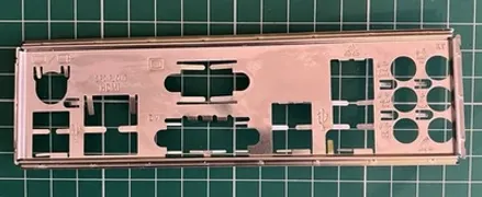 Motherboard IO Shield
Install the motherboard into the case standoffs
To do this, you first need to align the motherboard with the standoffs and lower it onto the standoffs. Once you have checked to make sure it is aligned correctly, you can then screw the motherboard in to the standoffs.
If aligned correctly, the motherboard should sit level with the case standoffs, and the IO ports should align with the IO Shield.
For cases which use the ATX form-factor, the standoff locations would be the same for all of them.
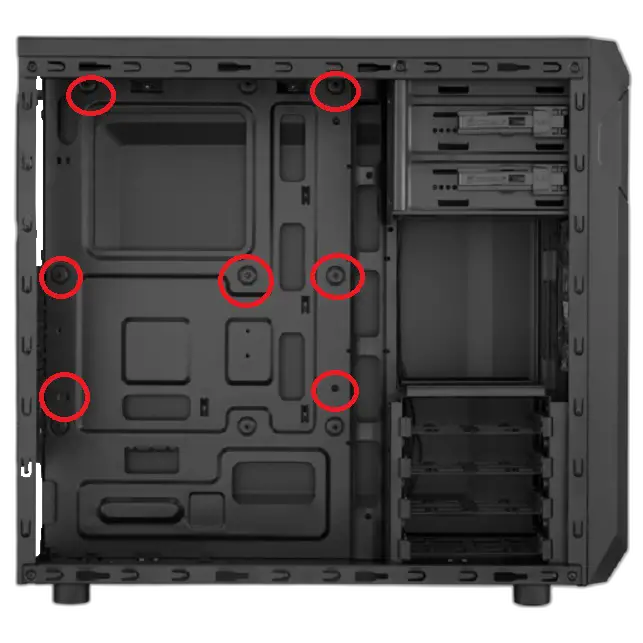 ATX Case Standoff Locations
Insert the CPU into the Motherboard socket
With the AM4 socket, a lever that is located on the right-hand side of the socket needs to be dis-engaged before inserting the CPU. Pull this lever gently out to the right and push it up slightly to unlatch it, now you are ready to install the CPU.
To install the CPU, pick the CPU up by the edges (do not touch the pins at the bottom of the CPU!), align the golden triangle on one corner of the face of the CPU to the indented triangle on one corner of the socket. Then insert the CPU into the socket.
The golden triangle and the triangle on the socket are there to ensure you will insert the CPU in the correct orientation.
Do not push the CPU into the socket! This can cause great damage to the CPU including bending the pins on the underside of the CPU, which will make your CPU inoperable and permanently damaged! If you have done everything correctly the CPU should just fall into place when being inserted into the socket with no resistance.
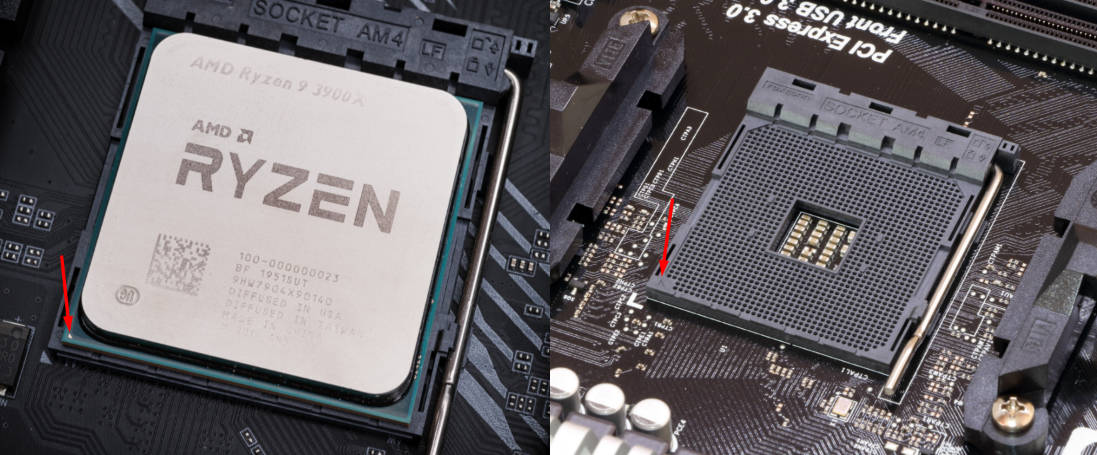 An image showing an arrow which points to the golden triangle on an AMD AM4 Ryzen CPU (left), and the indented triangle on the socket (right)
Install the CPU fan cooler
- Install the cooler brackets which screw in to the motherboard backplate supplied by the cooler
- Apply thermal paste on to the CPU
- Align the cooler with the brackets and place it on top of the CPU
- Secure the cooler bracket handles onto the brackets
- Plug in the cooler cable into the
CPU_FANheader on the motherboard (which is usually located somewhere in the top-right of the motherboard)
 Installed AMD AM4 CPU Fan Cooler
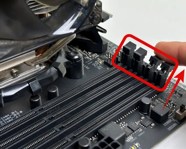
Install the dual-channel RAM sticks into the motherboard
If your motherboard has 4 memory slots, your RAM sticks would plug into either slots 1 and 3, or slots 2 and 4, consult your motherboard manual for where to put dual-channel RAM sticks, with dual-channel RAM, you can not directly plug the RAM sticks next to each other, unless your motherboard has 2 memory slots.
If the RAM you have bought has exposed circuitry, do not touch the exposed circuitry and only hold the RAM sticks by the edges.
In order to install the RAM, you first need to push the clips at the top (and sometimes bottom, depends on the motherboard) of the RAM slot down.
 Push the little clip/s at the top (and sometimes bottom) of the ram socket down
Then, match up the bottom connectors (the cutouts/pins) on the RAM module to the cutouts on the slot. Hold the RAM by both edges and gently push the RAM module down until you hear a click.
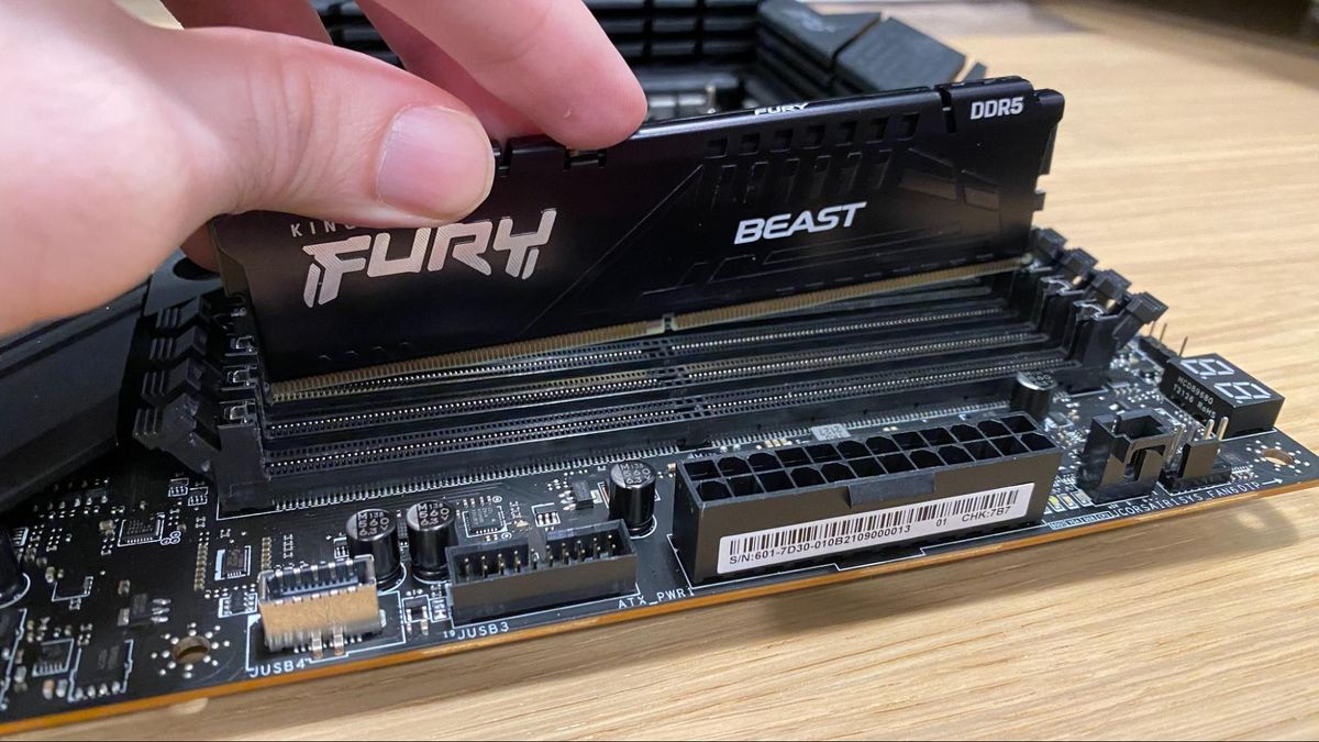 RAM stick insertion
If you did this correctly, the clips should automatically click back into their original place when the RAM has been inserted.
Install the GPU into the motherboard
Firstly, you will need to remove the PCI-E brackets on your case.
Once that is done, find a PCI-E x16 slot on your motherboard, open the retaining clip, and install the GPU into the slot. You will know that your GPU has been seated correctly if you hear a click and the retaining clip snaps back into its original place when inserting the GPU.
Install and connect the SATA SSD to the motherboard
This PC World article describes in great detail how to install SATA (and M.2) SSDs into a desktop PC
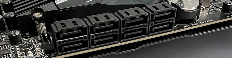 Closeup of the SATA ports on a motherboard
Install the Power Supply (PSU)
The general steps to install a PSU are as follows:
- Unscrew the PSU shroud at the back of the case
- Screw the PSU shroud on to the PSU
- Screw the PSU shroud into the case
Connect the Power Supply cables to the components
Asrock B450m-HDV r4.0 connector locations
- Connect the CPU cable to the connector on the motherboard
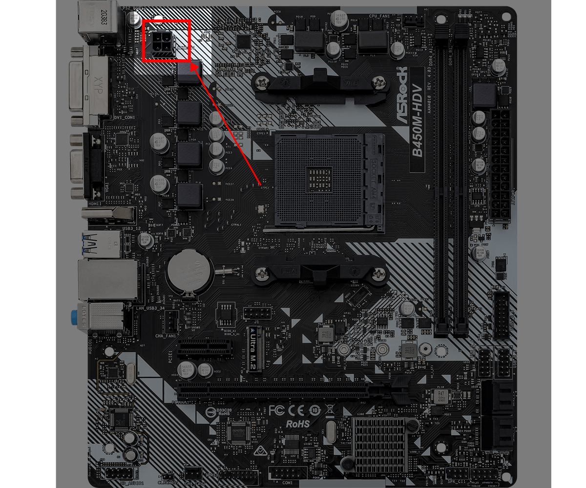 CPU cable header on an Asrock B450m-HDV r4.0
- Connect the Motherboard cable to the 24-pin connector on the motherboard
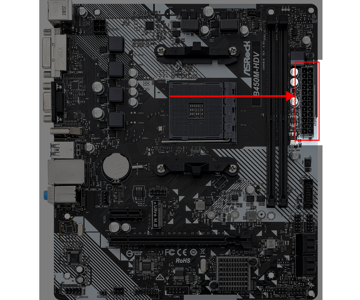 Motherboard cable header on an Asrock B450m-HDV r4.0
- Connect the GPU cable/s to the GPU
- Connect the Hard Drive power cable to the connector on the SATA SSD
Connect the case front-panel cables to the motherboard
You will need to plug these connectors in (see motherboard manual for connector locations):
- Power button
- Power button LED
- Hard drive LED
- USB 3.0 front panel connector
- HD Audio front panel connector